

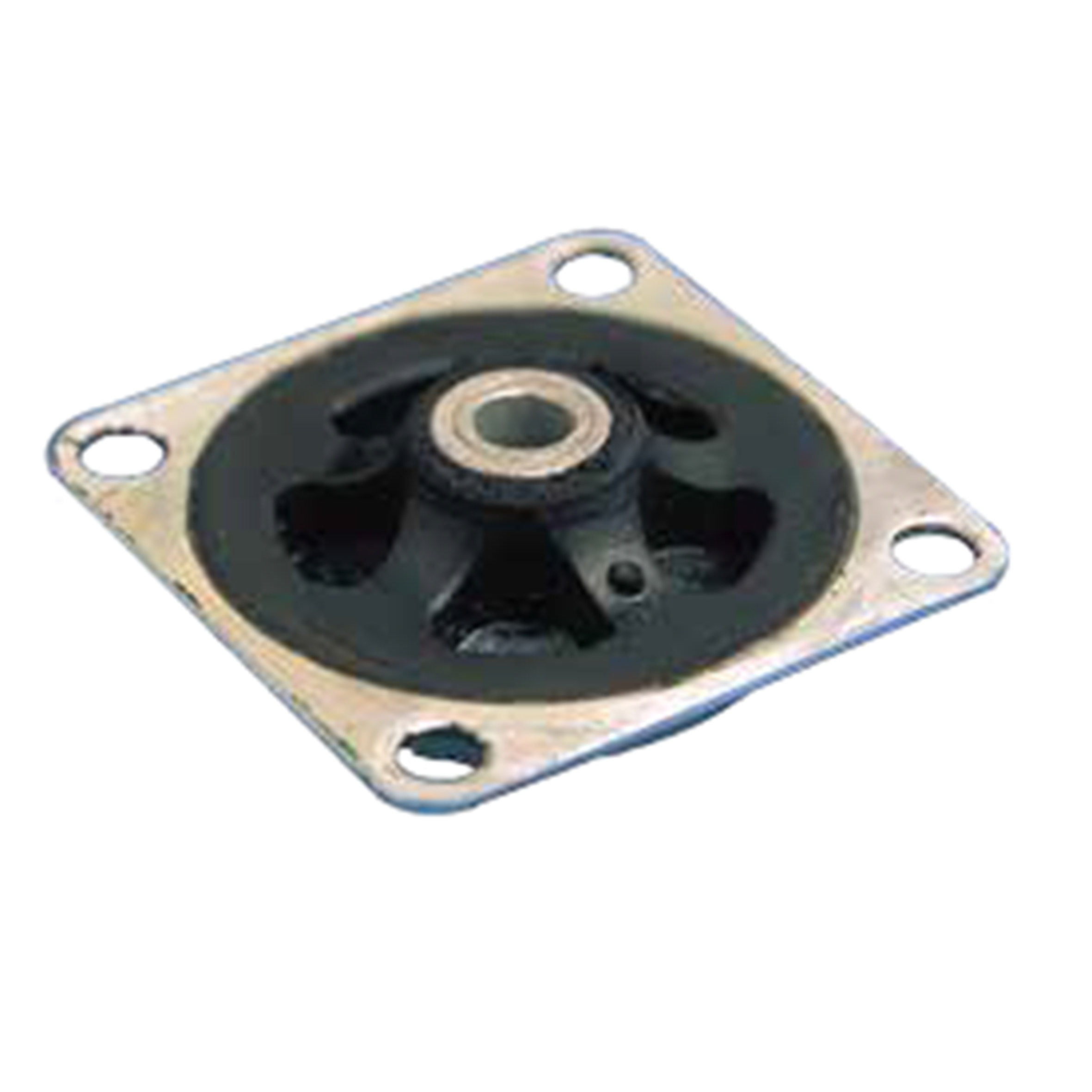
ISOFLEX Mount
The ISOFLEX® mount comprises two concentric metallic parts joined by a bonded, perforated rubber ring.
The design of the ISOFLEX® mount gives the following basic characteristics : elasticity approximately the
same in all directions (equi-frequent mounting).
APPLICATIONS
ISOFLEX® mounts may be used for suspending any small measuring or recording equipment,
mobile equipment, machine tool controls.
Natural frequency : 11 to 15 Hz
ASSEMBLY
To avoid toppling or canting, the suspension should be designed so that the centre of gravity
of the suspended equipment is close to the geometrical centre of the suspension.
TECHNICAL CHARACTERISTICS
All of our mounts are identified by conventional markings, either a paint spot or figures indicating the
of the suspended equipment is close to the geometrical centre of the suspension.
TECHNICAL CHARACTERISTICS
| Reference |
Nominal static load (daN) |
Deflection (mm) |
Type |
Hardness (Shore A) |
|
552428 552231 552231 |
0.25-1 0.50-2 0.75-3 |
3 3 2.5 |
R I.20 I.20 |
50 45 60 |
|
552241 552241 |
1-4 1.5-6 |
3 2 |
I.30 I.30 |
45 60 |
hardness : grey = hardness 45, green = hardness 60, blue = hardness 75.

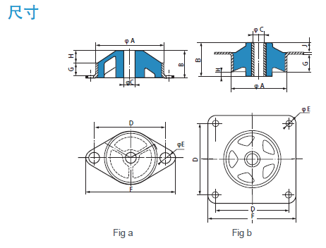
| Type | Fig | Reference |
硬 度 (Shore A) |
ФA (mm) |
B (mm) |
ФC (mm) |
D (mm) |
ФE (mm) |
F (mm) |
G (mm) |
H (mm) |
J (mm) |
Weight (g) |
| R | a | 552428 | 50 | 28 | 8 | 4,2 | 36 | 3,2 | 44 | 4 | 3 | - | 9 |
| I.20 | b | 552231 | 45-60 | 25,4 | 10,3 | 4,2 | 25,4 | 3,6 | 31,8 | 4,2 | 1 | 4,3 | 10 |
| I.30 | b | 552241 | 45-60 | 38,1 | 15,9 | 6,2 | 34,9 | 4,2 | 44,5 | 7,3 | - | 7,3 | 30 |